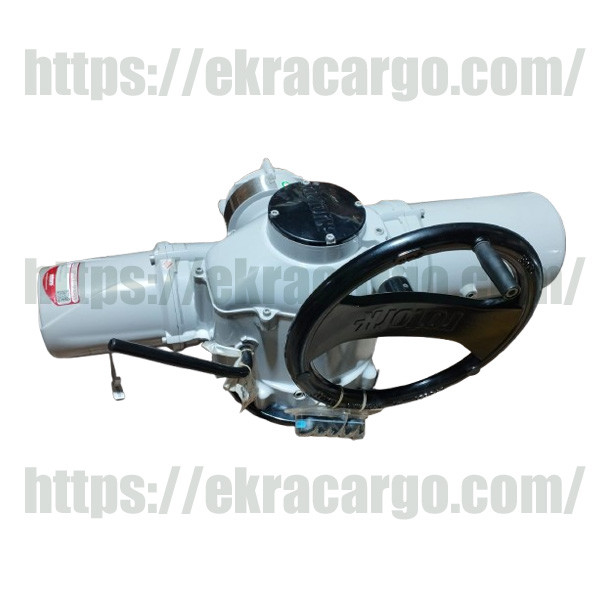
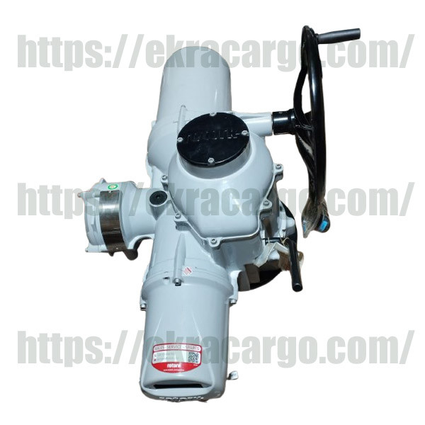
Rotork 1091 Electric Actuator Wiring Diagram: Basic Guide
The Rotork 1091 electric actuator wiring diagram is a crucial aspect to understand for proper implementation and functioning. Despite variations in different versions of the Rotork 1091, the general scheme in 1091 electric actuators is summarized below:
Check the similar product at Ekra Cargo
Power Supply Connection:
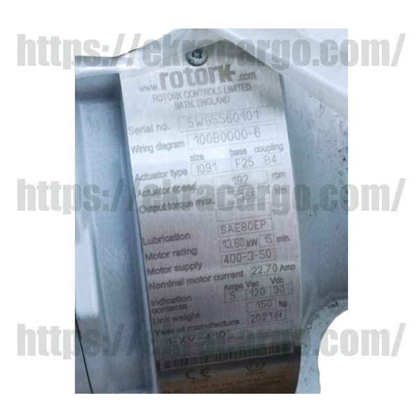
The actuator needs an input of either
three-phase or single-phase AC power (which could be either 230 V or 415 V,
depending on your model). The live connections (L1, L2, L3/N) and earth are
connected to corresponding terminals in the actuator’s junction box.
Motor Leads:
Motor windings will be wired from the motor terminal block present inside the Rotork actuator. The order of the phases is important to turn the motor in the proper direction. Which terminal is intended to go to the forward or clockwise direction or the reverse or counterclockwise direction will be shown in the wiring diagram. Control Signals: Low voltage control wires (start/stop, open/close, interlocks) connect into the control terminal block of the actuator. This will or may include connections for remote control panels, contactors, and PLC digital I/O as specified for polarity and signal, 24 VDC or AC.
Check the product at Ekra Cargo

Ekracargo.com - Your trusted partner in industrial efficiency, providing a wide range of premium quality spare parts at competitive prices.
Contact Info
- Address: House 54 | Road 14 | Sector 14 | Uttara | Dhaka 1230 | Bangladesh
- Phone: Contact: +8801634736139,+8801789394669 (WhatsApp)
- Email: info@ekracargo.com