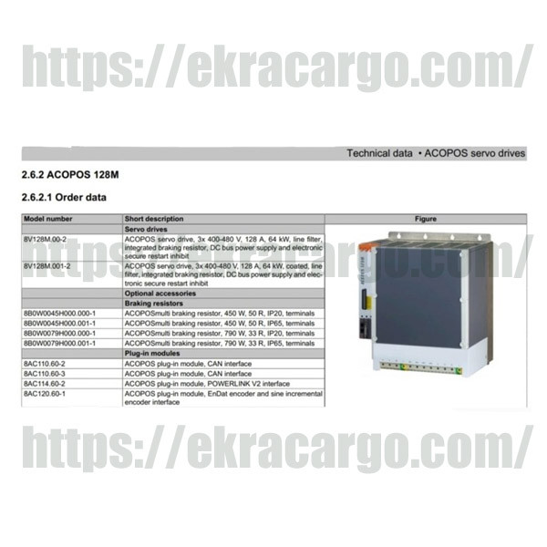
B&R ACOPOS Servo Drive Wiring Diagram: Basic Guide for Connections
The wiring diagram of the B&R ACOPOS servo drive is a significant reference in its installation as well as in connecting the drive with power supplies, motors, feedback sensors, or control systems.
Check The Similar Product At Ekra Cargo
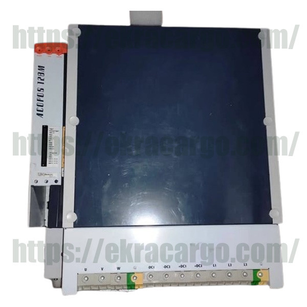
1. Connections of Power Supply
First, you will have to wire the main
DC link or AC inputs to the model of the drive. However, for most of the ACOPOS
drives, a line voltage of 230V or 400V three-phase has to be connected to the
corresponding L1, L2, and L3 terminals.
2. Motor & Feedback Wiring:
The power cable for the servo motor is
connected to the motor output terminals on the drive. The connection of the
encoder or resolver cables, for position and speed feedback, to the feedback
terminals on the drive is done.

3. Control Signals:
The B&R ACOPOS drives interface, through your PLC or motion controller, is by use of digital and analog inputs/outputs and a communication port like POWERLINK, EtherCAT, and CAN open, depending on the type.
Check the product at Ekra Cargo
4. Safety and Options:
If present in your
configuration, safety functions, like STO, connect the safety inputs as per the
approved schematic. In all cases, you have to refer to the official B&R
ACOPOS Servo Drive Wiring Diagram supplied in the product manual.

Ekracargo.com - Your trusted partner in industrial efficiency, providing a wide range of premium quality spare parts at competitive prices.
Contact Info
- Address: House 54 | Road 14 | Sector 14 | Uttara | Dhaka 1230 | Bangladesh
- Phone: Contact: +8801634736139,+8801789394669 (WhatsApp)
- Email: info@ekracargo.com